From the View menu, make sure Axes and Grid are unchecked and Algebra View is checked.
From the Options menu, select
Labeling > New Points Only.
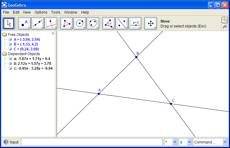
Select the Line tool
 and create the image shown to the
right.
and create the image shown to the
right.Hit the Esc key or select the Move tool
 . See how you can move the
points around. The points are "free" but the lines are dependent.
. See how you can move the
points around. The points are "free" but the lines are dependent.Also, you can drag the labels around for better visibility.
See how your points and lines are represented in the Algebra View on the left.
 ; see how
instructions for using the tool are displayed on the tool bar.
Use this tool to make a picture like the one on the right.
; see how
instructions for using the tool are displayed on the tool bar.
Use this tool to make a picture like the one on the right.If you need to delete an object you can select it then hit the Delete key.
To pan the worksheet, hold shift while dragging the mouse. Alternatively, the Pan tool
 is available.
To zoom in and out, use the mouse scroll wheel. Alternatively the zoom tools

 are available.
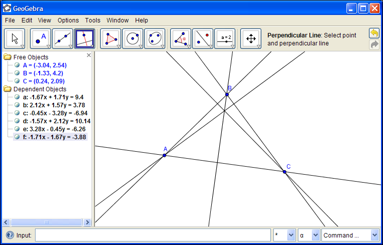
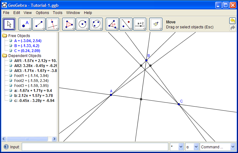
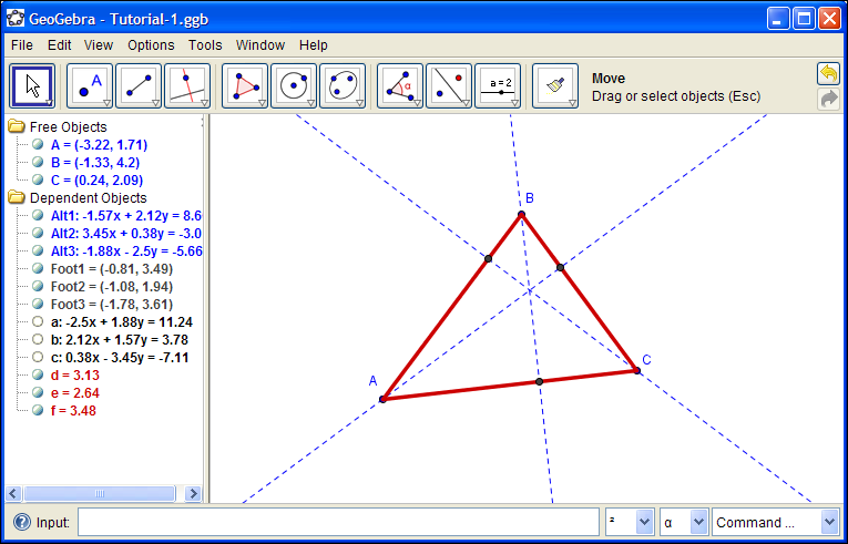
Now the labels Alt1, Alt2, Alt3 show up in the Graphics View. Right-click them and uncheck "Show Label."
Select the Point tool
 and click the points where
the triangle sides intersect with the altitudes. Rename these
points Foot1, Foot2, Foot3, and hide the labels.
and click the points where
the triangle sides intersect with the altitudes. Rename these
points Foot1, Foot2, Foot3, and hide the labels.It's a good habit to give your objects descriptive names.
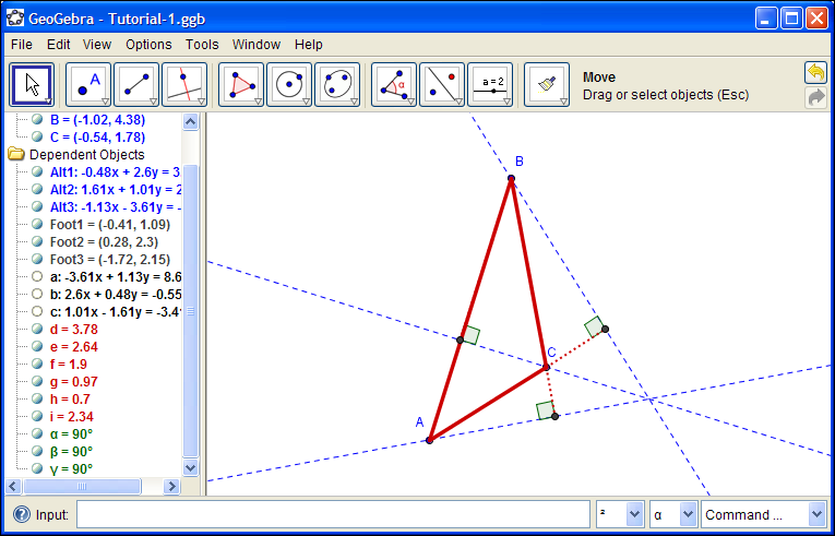
Ctrl-click Alt1, Alt2, Alt3 to select all three. Click the Color tab and choose blue. Click the Style tab and select a dashed line. Close the Object Properties dialogue box.

Connect points A, B, C with segments, using the Segment tool
 .
. Using Object Properties, make these segments red and increase their line thickness.
As you move points A, B, C around, the feet of the altitudes can move off the triangle segments. To obtain this effect we needed to define the triangle initial with lines instead of segments.
Select the Angle tool
 and put angle indicators at the
feet. Under Object Properties you'll want to modify these angles:
and put angle indicators at the
feet. Under Object Properties you'll want to modify these angles:- Hide the labels
- Uncheck the "Allow Reflex Angle" option
- Make smaller (make size = 20)